MIL-DTL-14055G
f. Determine the lip and base diameter of the secondary cup as installed on the piston and the
primary. The lip diameter of the primary and secondary cups shall be measured and recorded to
the nearest 0.001 in (0.02 mm), taking the average of two readings at right angles to each other.
The lip diameter of the secondary cup shall be measured after the cup has been assembled on the
piston.
g. Inspect the relief and supply ports of the master cylinder and discard the cylinder if their ports have
burrs or wire edges.
h. Measure the internal diameter of the cylinder at two locations: approximately mid-way between the
relief and supply ports and approximately 0.75 in (19 mm) beyond the relief port toward the bottom
or discharge end of the bore, taking measurements at each location on the vertical and horizontal
center lines of the bore.
i. Discard the cylinder if any readings exceeds maximum or minimum limits of 1.128 - 1.125 inch
(28.65 - 28.58 mm).
j. Dip the rubber and metal parts of the master cylinder, except the housing, in the fluid specified in
MIL-PRF-46176 and install them in accordance with manufacturer's instructions. Discard boot and
push rod assembly.
k. Manually stroke the master cylinder to insure that it operates easily. Install the master cylinder in
the simulated brake system.
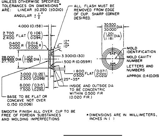
FIGURE 4. SAE test cup wheel cylinder.
16
For Parts Inquires call Parts Hangar, Inc (727) 493-0744
© Copyright 2015 Integrated Publishing, Inc.
A Service Disabled Veteran Owned Small Business